 01
01Diverting at Elevator and Conveyor Outlets
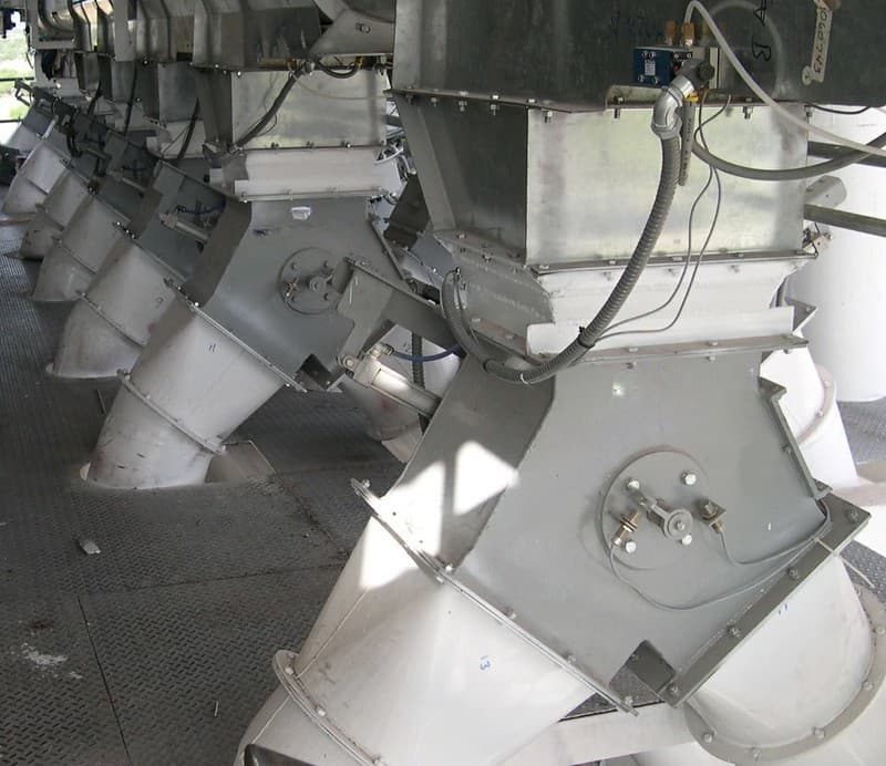
Sending product from an elevator or conveyor to two different lines. The diverter is connected directly to the conveying equipment outlet.
Bucket ElevatorIndustrial Plant Solutions
PRO MAKINA · Flap Diverter Valve
Overview
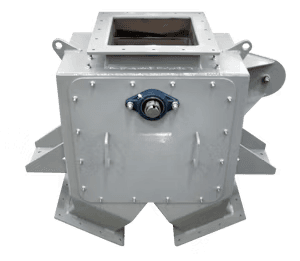
A flap diverter valve is flow equipment that directs bulk material from a conveyor, elevator or bunker outlet to one of two outlet lines. The flap pivoting on a shaft inside the body closes one outlet while opening the other; the product flows by gravity into the open line.
The flap is moved between its two end positions by a handwheel or lever, a pneumatic cylinder or a rotary actuator. End-position switches report to the automation which outlet the flap is set to.
Body section, flap geometry and outlet angles are determined by the product flow. The surfaces on which the flap seats are designed to limit product leakage and build-up; wearing parts are replaceable.
01Process Flow
The diagram shows the product arriving at the diverter inlet, the flap set to the selected outlet and the product transferred to the relevant line. Conveyor, elevator and target lines are separate equipment.
Scroll horizontally to view the full diagram.
Flow to inlet: Product arrives at the diverter inlet from a conveyor, elevator or bunker outlet.
Flap position: The actuator sets the flap to one of its end positions; the other outlet closes.
Position check: The end-position switch confirms the flap is at the correct outlet.
Transfer to line: Product flows by gravity through the open outlet to the selected line.
The flap position is changed after the feed has been stopped rather than under flow, so the flap is not forced against the product load.
02Applications
01Sending product from an elevator or conveyor to two different lines. The diverter is connected directly to the conveying equipment outlet.
Bucket Elevator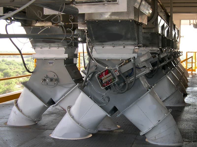 02
02Taking product from a row of bunker or silo outlets into one of two lines. End-position switches on each diverter are wired to the automation.
Silo Systems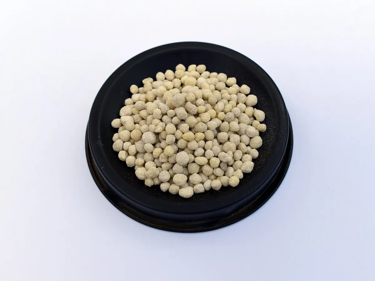 03
03Directing granular product between the product line and the recycle line. For abrasive products the flap and seating surfaces are made replaceable.
Fertilizer and Granulation Plants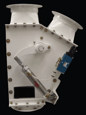
03Design & Manufacturing
PRO MAKINA engineers flap diverter valves around the product, flow section, outlet angles, actuation type and position control requirement. Body, flap, shaft bearings, sealing and wear parts are designed together.
Product
Product type, particle size, bulk density, abrasiveness and tendency to stick.
Section and Angles
Inlet section, outlet angles and layout of the connected lines.
Flap Geometry
Flap size, seating surfaces and sealing against product leakage.
Actuation
Handwheel or lever, pneumatic cylinder or motorised actuator.
Control
End-position switches, automation signals and maintenance access.
Section, outlet angles and actuator sizes are defined from product and line data; no generic values are stated on this page.
04Gallery
05FAQ
It directs bulk material from a single inlet to one of two outlet lines. The flap closes one outlet while opening the other.
The flap is moved by a handwheel or lever, a pneumatic cylinder or a rotary actuator. The choice depends on switching frequency and automation requirements.
A flap diverter directs the flow between two lines. A slide gate opens or shuts off the flow at a single opening with a sliding plate.
A rotary distributor is used for selection among many outlets, or flap diverters are arranged in series according to the line layout.
Product type and bulk density, particle size, flow rate, inlet section, outlet angles, actuation type and automation requirements.
06Resources
Technical Quotation
Share your product, line section and outlet layout, and we will define the flap diverter valve together with you.
This site uses cookies required to run the website securely and correctly. With your consent, additional cookies may be used for performance measurement, user experience and marketing. For details see the Cookie Policy and Privacy Policy pages.