 01
01Pneumatic Conveying Lines
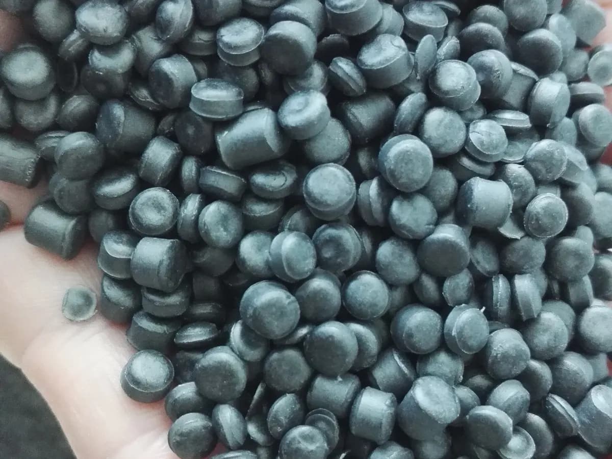
Conveying powders and granules with air through a pipeline. Product is fed into the line by a rotary airlock; the blower supplies the conveying air.
Rotary Airlock ValveIndustrial Plant Solutions
PRO MAKINA · Blower
Overview
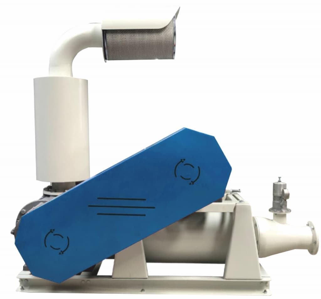
A blower supplies pneumatic conveying and air-assisted transfer lines with the required air flow at a pressure that overcomes the line resistance. Ambient air is drawn through the inlet filter, pressurised in the blower and delivered through the discharge line to the pneumatic conveying line.
In a Roots-type blower, two lobes rotate in opposite directions inside the casing without touching each other. Air trapped between the lobes and the casing is carried from the inlet to the discharge side. Being positive displacement, the air flow depends largely on speed, while the pressure builds up according to the resistance of the line and the conveyed product.
The inlet filter protects the rotors from dust; inlet and discharge silencers reduce operating noise. The relief valve on the discharge line keeps the pressure from exceeding the permissible limit if the line blocks.
01Process Flow
The diagram shows ambient air drawn through the inlet filter, pressurised in the blower, passed through the discharge line with silencer and relief valve, and feeding the pneumatic conveying line. Rotary airlock, conveying line and silo are separate equipment.
Scroll horizontally to view the full diagram.
Air intake: Ambient air enters the blower through the inlet filter and silencer.
Pressurising: The rotating lobes carry the air from the inlet to the discharge side.
Discharge line: Air passes the discharge silencer; the relief valve limits overpressure.
Pneumatic line: Pressurised air feeds the conveying line into which product is fed by an airlock.
Blower air flow and pressure are determined by considering the conveyed product, conveying distance, line diameter and bends along the route together.
02Applications
01Conveying powders and granules with air through a pipeline. Product is fed into the line by a rotary airlock; the blower supplies the conveying air.
Rotary Airlock Valve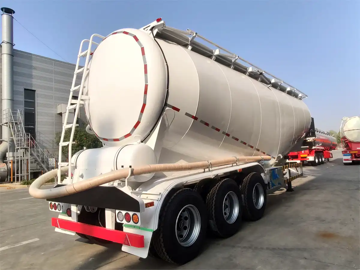 02
02Taking powder into a silo through a pneumatic line and providing air support for bulk tanker unloading lines. The filter on the silo vents the conveying air.
Silo Systems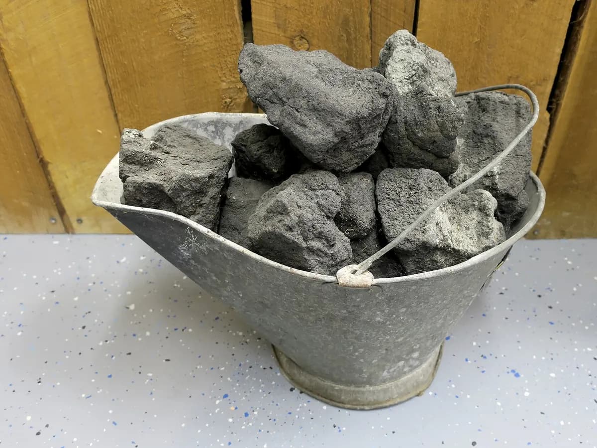 03
03In-plant pneumatic transfer of lime, cement-like products and mineral powders. For abrasive products, line velocity and bends are assessed together.
Mining and Mineral Processing03Design & Manufacturing
PRO MAKINA selects blower packages for the air flow and pressure required by the pneumatic conveying line and engineers them together with the line. Blower, motor and belt drive, inlet filter, silencers, relief valve and base frame are considered together.
Air Flow
Required air flow from the conveyed product quantity and line diameter.
Pressure Difference
Resistance from line length, bends, elevation and product load.
Motor and Speed
Blower speed, motor power and belt drive matched to flow and pressure.
Operating Environment
Ambient temperature, dust, intake air quality and noise limit.
Line Integration
Rotary airlock, conveying pipe, silo filter and automation connections.
Air flow, pressure and motor power are calculated from line and product data; no generic values are stated on this page.
04FAQ
It supplies pneumatic conveying and air-assisted transfer lines with air at a pressure that overcomes the line resistance.
Two lobes rotating in opposite directions inside the casing without touching carry the trapped air from inlet to discharge. Air flow depends largely on speed; pressure builds up according to the line resistance.
A cyclone or filter exhaust fan moves a large air volume at a low pressure difference. A blower delivers air at a pressure that overcomes the resistance of a pneumatic conveying line; the two are not interchangeable.
If the line blocks, a positive displacement blower keeps raising the pressure. The relief valve keeps the pressure from exceeding the permissible limit, protecting blower and line.
Conveyed product and quantity, conveying distance and route, line diameter, operating environment and details of any existing airlock or silo filter.
05Resources
Technical Quotation
Share the product, distance and route data of your pneumatic conveying line, and we will define the blower package together with you.
This site uses cookies required to run the website securely and correctly. With your consent, additional cookies may be used for performance measurement, user experience and marketing. For details see the Cookie Policy and Privacy Policy pages.