 01
01Below Cyclones
Removing dust separated in a cyclone from the cone outlet. The airlock limits air drawn in through the cyclone outlet by the fan suction, preserving separation efficiency.
Cyclone SeparatorIndustrial Plant Solutions
PRO MAKINA · Rotary Airlock
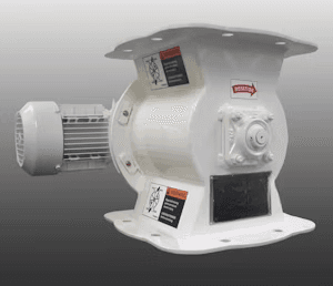
Overview
A rotary airlock is rotary valve equipment that transfers powders and granules from a cyclone, filter or bunker above to the line below while limiting air passage between the two zones. The cyclone or filter body is usually at a different pressure from the line below because of the fan suction; the airlock lets product flow downward despite this difference.
Pockets are formed between the vanes of the rotor turned by a geared motor inside the body. A pocket filled at the inlet opening reaches the bottom outlet as the rotor turns and discharges the product. The narrow clearance between rotor vanes and body limits air passing with the product.
Air leakage is related to rotor-to-body clearance, pressure difference and rotor speed. With abrasive products this clearance grows over time. Rotor and body materials, rotor geometry and speed are therefore selected for the product and pressure difference.
01Process Flow
The diagram shows product entering the airlock from below a cyclone, filter or bunker, rotor pockets taking and turning the product and discharging it into the line below. Cyclone, filter and downstream line are separate equipment.
Scroll horizontally to view the full diagram.
Product inlet: Product from below a cyclone, filter or bunker flows into the inlet.
Pockets fill: Rotor pockets at the top position fill with product.
Rotor turns: The geared motor turns the rotor; filled pockets move to the outlet.
Transfer downstream: Product discharges into the conveyor, screw or pneumatic line below.
Pressure difference: A difference caused by the fan or pneumatic line exists between upper body and lower line.
Limited air passage: The rotor-to-body clearance limits air passing with the product.
When feeding into a pressure pneumatic conveying line, the difference between line pressure and the inlet side is assessed separately in the design.
02Applications
01Removing dust separated in a cyclone from the cone outlet. The airlock limits air drawn in through the cyclone outlet by the fan suction, preserving separation efficiency.
Cyclone Separator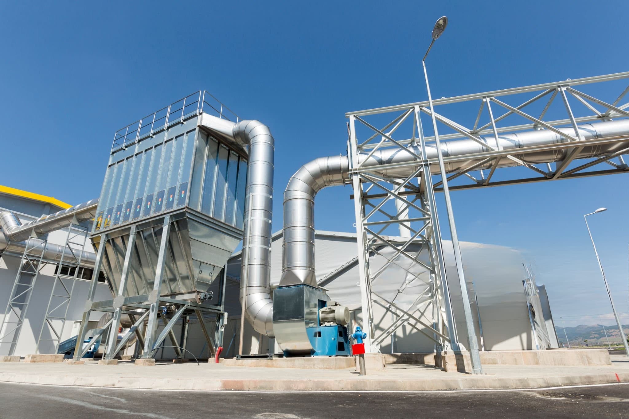 02
02Discharging dust cleaned off the filter bags from the hopper. The airlock limits air passage between the filter body and the line below.
Pulse-Jet Filters 03
03Feeding powders and granules into a pneumatic line driven by blower air. Line pressure is decisive in rotor selection.
Blower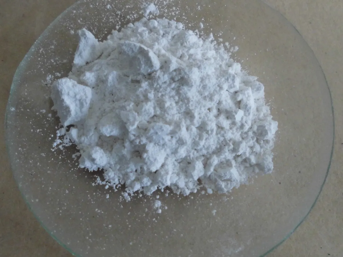 04
04Enclosed discharge of dusty product from a bunker or hopper to downstream equipment. Rotor speed is selected for the flow the downstream equipment can accept.
Bunkers & Hoppers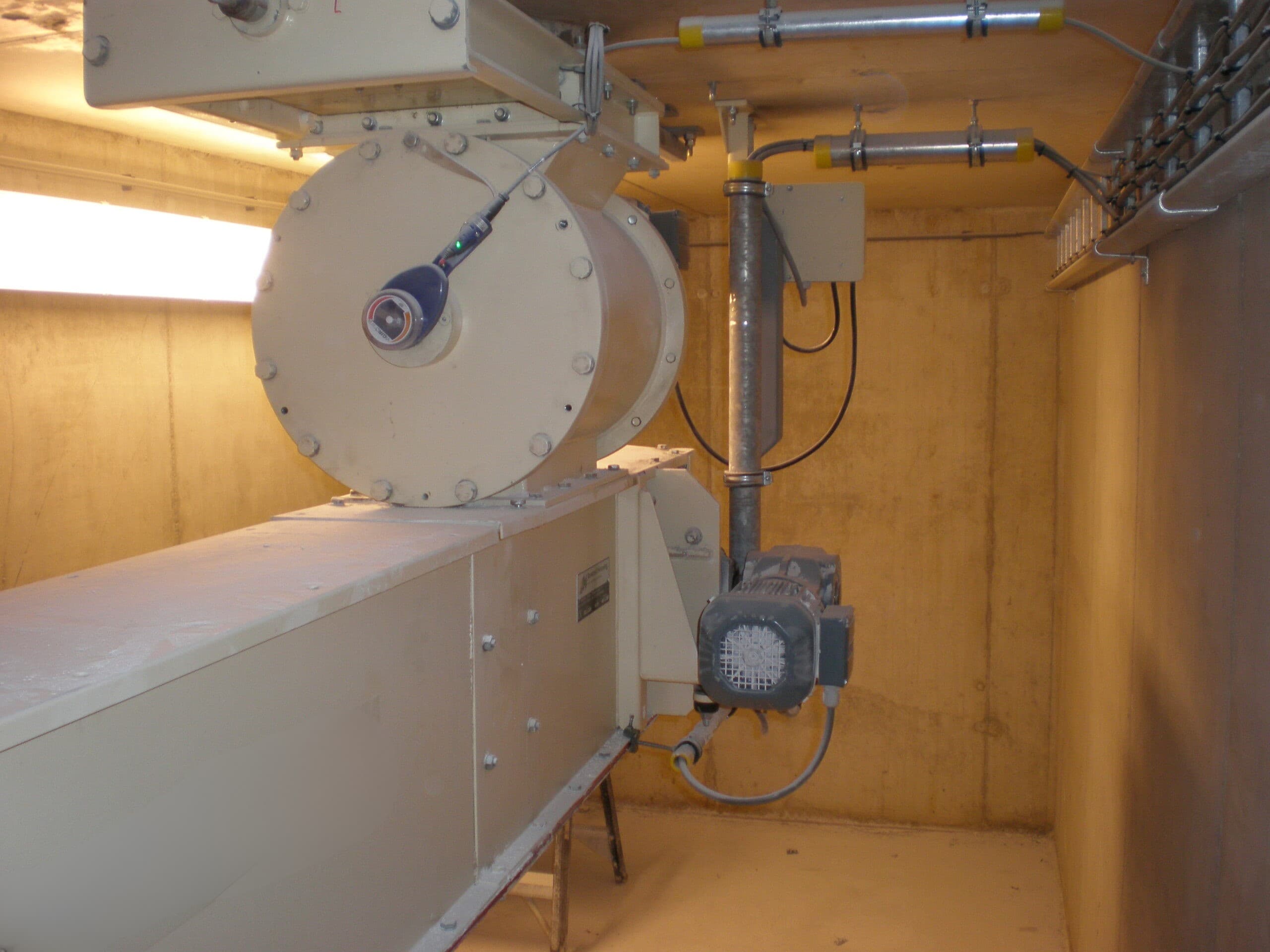
03Design & Manufacturing
PRO MAKINA engineers rotary airlocks around the product, required discharge capacity, pressure difference and connection dimensions. Rotor geometry, pocket volume, rotor-to-body clearance, speed and drive are selected together.
Product
Product type, particle size, bulk density, abrasiveness and tendency to stick.
Capacity and Speed
Required discharge capacity, pocket volume and rotor speed.
Pressure Difference
Difference between upper body and lower line and permissible air leakage.
Rotor and Body
Rotor geometry, number of vanes, clearance and material selection.
Connection and Maintenance
Inlet and outlet flanges, drive arrangement and maintenance access.
Rotor size, speed and capacity are defined from the product and pressure difference; no generic values are stated on this page.
04FAQ
It discharges product from below a cyclone, filter or bunker into the line below while limiting air passage between the two zones.
Pockets of the rotor turning inside the body fill with product at the top, move down as the rotor turns and discharge. The narrow clearance between rotor and body limits air passage.
No. Rotor speed affects the discharged volume, but the product is not weighed and pocket filling depends on product flow. For precise gravimetric feeding a weighing dosing system is used.
If air enters through the cyclone outlet, separation efficiency falls and dust is re-entrained. The airlock limits this air ingress while removing the separated dust.
Product type and bulk density, particle size, discharge capacity, pressure difference, temperature, connection flanges and the equipment it will be fitted to.
05Resources
Technical Quotation
Share your product, discharge capacity and pressure difference, and we will define the rotary airlock together with you.
This site uses cookies required to run the website securely and correctly. With your consent, additional cookies may be used for performance measurement, user experience and marketing. For details see the Cookie Policy and Privacy Policy pages.